Ways to keep your machinery fleet in top condition
Across the industry we appreciate that turfcare equipment is becoming more technically advanced.
Engines are becoming more environmentally cleaner and are incorporating more sophisticated sensors and engine management systems.
New hybrid and electric machines incorporate both 12‑volt and 48‑volt systems with electric controllers, CAN bus systems and built in diagnostic capabilities. We’re seeing evolving cutting units, electrically driven motors, changes in reel geometry, different set up and bottom blade angles and all of this progression requires a high level of skill and knowledge to manage and maintain.
If you don’t have a dedicated mechanic you may be thinking about, or already are, maintaining your machinery fleet yourself. This year we are finding ourselves in unchartered water, with the need to maintain our own machinery as lockdown disrupts the availability of a visiting technician.
As a professional industry, before picking up a spanner or screwdriver, it’s important we understand our legal obligations when working on turf machinery.
The provisional use of work equipment regulations states “anyone maintaining work equipment must have had adequate training”.
Therefore it’s important you consider the training you have undertaken or have a plan in place to give adequate training on the maintenance and repair of your turfcare equipment.
For formal training there are options available to end user » customers and college‑delivered machinery maintenance apprenticeships are widely available. These courses deliver structured maintenance topics with some specifically based on turfcare machinery.
Outside of a structured apprenticeship, emphasis has been placed on the machinery manufacturer to provide customer training, either directly or through dealer networks. I have been involved in planning and delivering manufacture training for nearly two decades and fully understand this training. Rightly so, this training is product specific to the manufacturer delivering it.
This training, although not always backed up by a recognised awarding body, will be classed as ‘adequate’ training. It will also utilise the most recent products, which is an important factor if you have recently purchased a new machinery fleet.
Recently, with the development of specific turfcare machinery maintenance courses, there is the option to attend nationally‑recognised, certificated, short one‑day modular courses to help maintain your machinery. This training is not brand specific, an important factor for customers with both old and new machines and those that have more than one manufacturers machines in their fleet.
Clive Pinnock, a very good friend and mentor, once told me that the first step in machinery maintenance is to understand how the machine works. Once you know what should be happening it is easier to identify faults when normal functions fail. This has helped me through some difficult diagnostics and it is good advice I now pass on to my customers when training.
From greenkeepers that want to know the basics on how to maintain their machinery fleet, to part time or full‑time course mechanics, here are some steps to help you with machinery diagnostics:
Understand the functionality of the machine
Let's take an issue such as cutting unit lifting or lowering on a Toro RM6500. The issue reported is the front middle and both rear units are stuck in the raised position. The outside front units, left and right, will lift and lower OK.
To diagnose the issue, we need to understand the machine from both a greenkeeping and mechanical prospective. As greenkeepers we know that on a good machine all five units do not raise or lower at the same time. There is a delay between the front units and rear units, which helps achieve a more even start/stop cutting position between front and rear units.
From a mechanical perspective we know there needs to be an engineered function/state to allow this to happen. In the case of the RM6500 it is a proximity switch on the front left‑hand unit lift arm. RM5010 units have it located on the right front unit lift arm.
This type of switch is an inductive proximity switch that detects metal objects. It is on the machine to detect the lifting and lowering of the front unit carrier arm. If this switch is faulty, the electronic control unit on the machine will not know when the front units are raised or lowered and may not lower the rear units to indicate the fault.
As a service manager I had these symptoms reported to me on an RM6500 but the fault was intermittent. Visiting the customer, I tested the switch with a test meter and it functioned correctly. As we lifted the units up and down, I applied pressure to the lift arm, pushing the unit back, and it worked every time. On further inspection I found the wrong size pin in the swing arm. This allowed for a slight play, which was enough to stop the proximity switch working, but not every time.
Understanding what is required as a greenkeeper and mechanical functionality focuses us onto the fault. This will then help us to diagnose the cause and potentially fix the issue.
Familiarise yourself with onboard diagnostics
With the introduction of diagnostic capabilities on modern turfcare machinery, diagnostics of electrical issues is now much easier for the customer.
Having said that, I know for most people these onboard diagnostic tools are still viewed as something that is complicated. Most of my training is designed to explain and demonstrate how these controllers are not complicated. It’s very rewarding to see people understand how easy it is to diagnose issues using these electrical systems on modern turf machinery.
When training, I still find customers that view the diagnostic light on the older RM5010 series as just an engine warning light. This light is a diagnostic tool to access fault codes through the Electric Control Unit (ECU). Customers can go through a simple procedure to access the ECU diagnostics.
Once accessed the light will blink the number that relates to the fault if a fault is present. This can be helpful in finding the fault or relaying the information to your dealer when asking for assistance.
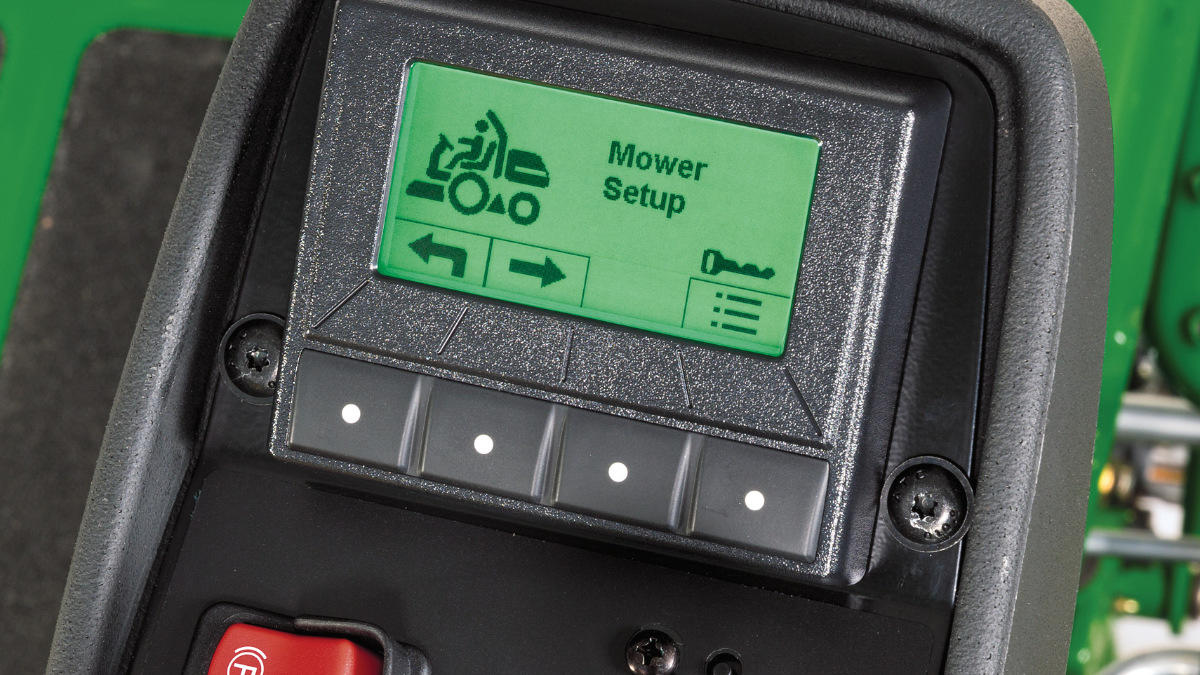
Of course, the newer capabilities, like the John Deere Tech Controller and Toro Info Centre, make it even easier by showing the information on a visual display. Customers can easily access the diagnostic area and check the electrical function of the machine.
A useful tip to understand what is happening when we go into diagnostics on these types of units is: a switch is an input into the ECU, a command to the ECU to activate something.
When testing inputs via a controller we are verifying the switches (commands) are functioning. Once the ECU receives a command it activates an output, an action.
When testing outputs via a controller we are verifying the action created by the input is functioning.
At this point, using the diagnostics we are generally testing continuity and further testing will be required to verify the correct resistance at output functions such as solenoids. A working understanding of test meters is required, which can be achieved through fundamental training available on one day courses.
Understand schematics
An important but under‑used aspect of fault finding and diagnostics is to make sure we are comfortable with reading schematics.
Schematic diagrams of electric or hydraulic circuits can be found in the service manual for your machinery.
To make life easier for me when diagnosing faults, I have laminated A3 copies of a schematic so that I can see what I am looking at much clearer. As they are laminated, I can use a dry wipe marker to trace the route I want to investigate and wipe clean when finished.
When I teach electrics or hydraulics, the first comments I get when reviewing schematics is always the same: the schematics are confusing and look complicated. To overcome this, we need to break down the system on the schematic diagram to the area we are troubleshooting. This allows us to disregard the systems that are working and concentrate on the smaller subsystem, where the fault is likely to be. Doing this makes the schematics look less confusing and will aid in our troubleshooting process.
What if we looked at the schematic diagram for hydraulics on the RM5410 and applied this theory regarding an issue with raising the cutting units?
Let’s assume, using the onboard diagnostics, that we have ruled out an electrical issue. Using the schematics, we would see that to raise all five units solenoid valve SV2 needs to function correctly.
This allows flow to solenoid valve SV3 and solenoid valve SV1. We would see from the schematic that both the rear cutting units are activated by solenoid valve SV3 with the front cutting units activated by solenoid valve SV1.
If the issue was all five units, we can concentrate our efforts on SV2.
Likewise, if the fault is with the rear units or the front three units, we can concentrate on either SV1 or SV3. Five minutes reviewing the schematics, whether hydraulics or electrics, can focus us onto the correct subsystem and potentially save time, effort and money, resolving the issue.
Test components
I often come across technicians that systematically replace components in a system until the issue is resolved. I refer to this type of diagnostics as ‘swopnostics.’ Although there is no doubt that replacing components can be part of the diagnostic process, it should not be the main troubleshooting basis for diagnosing issues.
Once you are familiar with the functionality of the machine and you have checked the onboard diagnostics and used the schematic diagram to identify possible faults, it then comes down to using skills to physically check and replace components.
If we follow a methodical approach of working through the schematic diagram and focusing on the sub system it is a certainty that we can isolate the potential issue.
Once isolated we can now identify the components that need testing and either find a faulty component or eliminate it as working correctly.
When verifying components are working, utilise tips such as relays clicking to identify they are energising and engaging or placing metal onto a solenoid to see if they are magnetising when energised. This will be a good indication as to whether they are working or not.
If components are functioning OK, we need to take our testing a step further, which requires the use of a test meter. These can be relatively inexpensive and straightforward to use when checking continuity, voltage or resistance.
With the nature of turfcare equipment, working in all weather conditions and exposed to the elements, it is common to have earthing/grounding issues. Many think that as long as the ground wire is touching some part of the vehicle, it is grounded, but that is not the case. You must make sure the ground wire is attached at a point that is free of paint, rust, or plating.
When you purchase equipment it can be common to find that paint on the chassis or body panels acts as an insulator, resulting in a bad ground connection. The easy fix is to remove the excess paint to give a better earth.
Being a turfcare machinery technician is not easy. You need to understand electrics, hydraulics and agronomy, as well as cutting unit sharpening and infinite set up scenarios to achieve the quality finish you and your golfers expect.
Fully understanding modern turfcare equipment is not something that we can treat lightly and view as a hobby. As I first mentioned, the law states “anyone maintaining work equipment must have had adequate training”, but it is also worth considering that the right training can develop your current ability, build confidence and reduce the potential for costly mistakes.
Author
